UVM Environment
We saw earlier in previous sections how a test contains an environment and creates it. In this section, we will see what all components are created inside a UVM Environment and how they communicate with each other using Transaction Level Modeling ports and FIFOs.
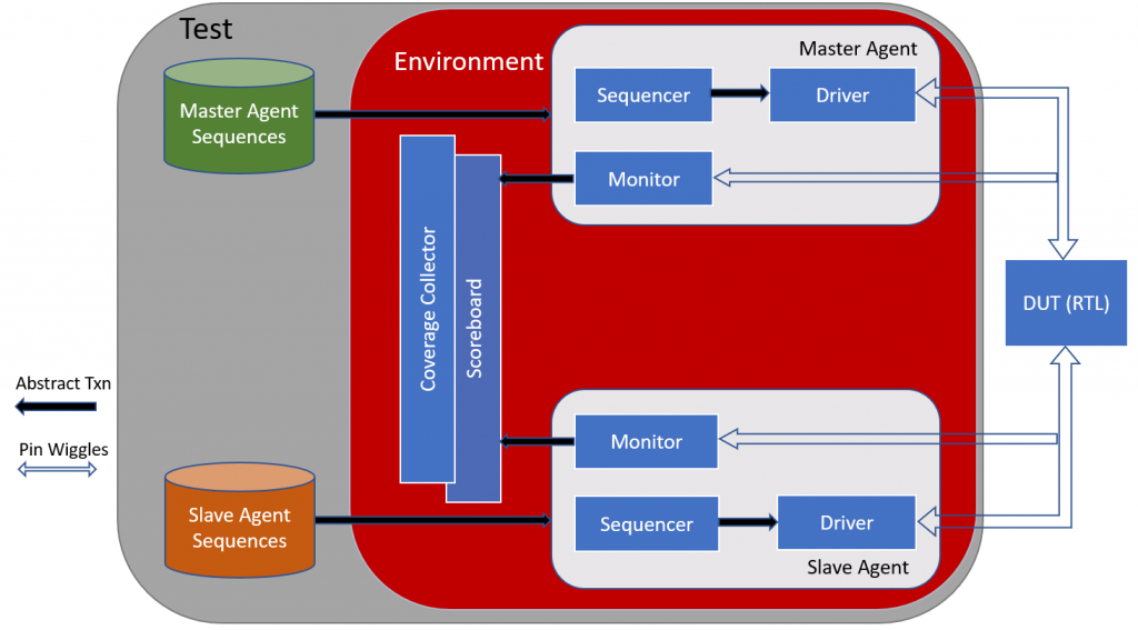
A UVM Environment instantiates all agents associated with the design. A verification engineer can model the environment in such a way that each interface of the Design has a corresponding UVM agent and the UVM Environment contains all these agents. Coverage Collector and Scoreboards are also instantiated inside UVM Environment.
Below is a sample code snippet for a UVM Environment:
class env extends uvm_env;
`uvm_component_utils(env)
add_scoreboard scbd;
add_Agent agt;
add_coverage cov;
function new(string name, uvm_component parent)
super.new(name, parent);
endfunction
function build(string name, uvm_component parent)
//Build agent,scoreboard, coverage collector
scbd = add_scoreboard::typeid::create(“scbd”, this)
agt = add_Agent::typeid::create(“agt”, this)
cov = add_coverage::typeid::create(“cov”,this)
endfunction
function connect(string name, uvm_object parent)
super.connect();
//Connect monitors ap with scoreboards analysis fifo
add_monitor.mon_ap.connect(add_scoreboard.actual_port);
add_driver.drv_ap.connect(add_scoreboard.expected_port);
endfunction
endclass
In above sample code snippet, env class is defined by extending it from standard UVM class uvm_env. The class is then registered to the factory using macro `uvm_component_utils. As seen in above diagram Environment contains Scoreboard and Agents. So in this sample code, we first create handles to add_scoreboard and add_Agent classes with name scbd and agt respectively. Then like any other uvm component class, define constructor. After that, inside the build function, we create or instantiate sbcd and agt objects using standard UVM function create. This is when actual memory allocation for these object happens. So remember, first we declared the handles and then inside the build function, we created the actual uvm components.
After that, monitor is connected to scoreboard‘s analysis FIFO and Driver‘s analysis port is connected to Scoreboard’s analysis port which is called expected port inside the connect function. Monitor continues to look for a transaction on DUT interface and as soon as any transaction appears on interface, monitor sends it to scoreboard. This communication between monitor and scoreboard happens with the help of TLM (Transaction Level Modelling). The driver also sends the expected transaction to scoreboard using TLM. When scoreboard receives the data from Driver and the monitor, it compares the expected data with actual data and there is a mismatch, scoreboard reports an error.
To get notifications for our upcoming blogs and tutorials, please LIKE our facebook fan page